Module ui
ToggleUI
The stacktoggle is a device that can be used to control physical I/Os that are available in the industrial environments like automatic roll up doors, traffic lights, button inputs, etc. The stacktoggle provides a web based UI that is accessible via toggle's local network, and allows for a convenient way to connect it to site's network infrastructure.
Status page
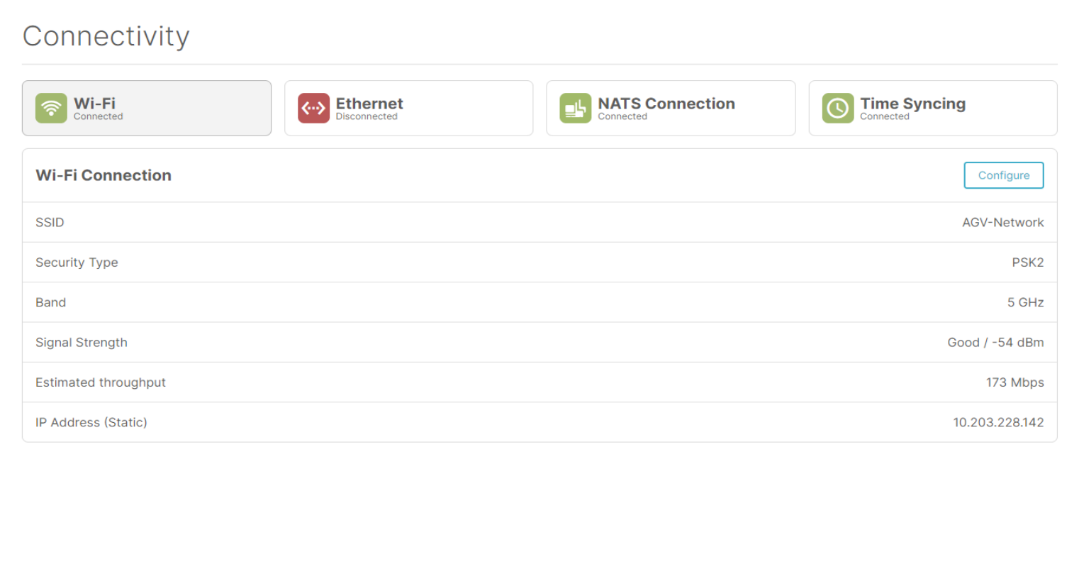
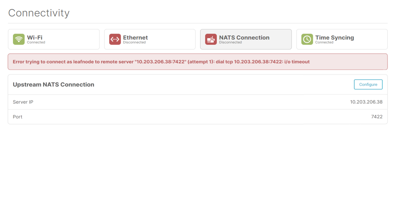
The connectivity status page gives a clear overview to the user about the different connections on the toggle. We consider 4 different connections. The toggle can be connected with Wi-Fi or Ethernet. Besides that, we also have the NATS connection. This is the NATS leaf node configuration for connecting to the fleetmanager. The last connection is the 'Time syncing' connection. This is the connection between the NTP on the toggle and an upstream NTP server.
The user will be able to see at a glance the status of the different connections. This is achieved with the different status icons at the top of the screen. The icons can have 3 colors: green, orange and red. A green icon means everything is fine, and the connection is working properly. An orange icon means that the connection is trying to connect. A red icon indicates an error with the corresponding connection. A red error message will indicate what could be wrong with the connection configuration.
The tiles with the status icons at the top also act like tabs, so the user can click on them to get more details about that specific connection.
Wi-Fi status
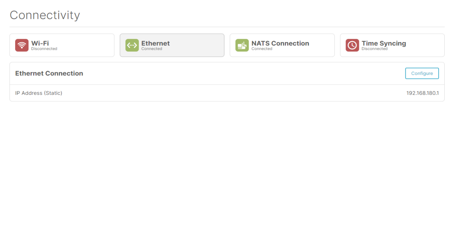
Ethernet status
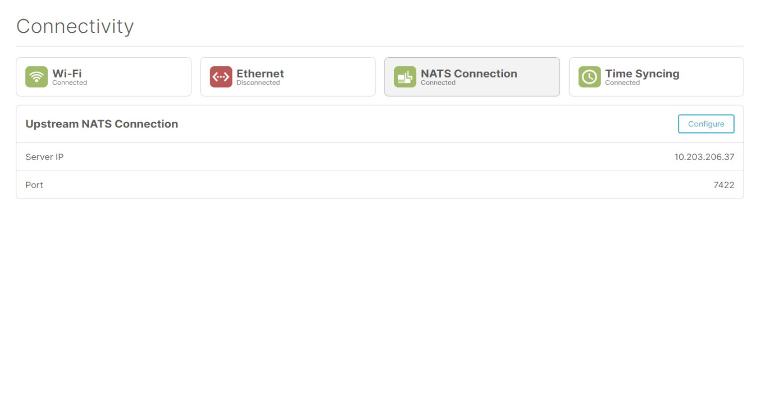
NATS status
Time syncing status
Disabled state
When a connection isn't configured yet, it will get the 'Disabled' state. This means the connection is currently not used and needs some setup to start working. When a connection is disabled, the user can click the 'Configure' button in the details panel to configure the connection.

Setup wizard
When the user selects a connection on the status bar, the details panel at the bottom will contain a 'Configure' button. If you click this button, the setup wizard for that specific connection will be started.
Wi-Fi
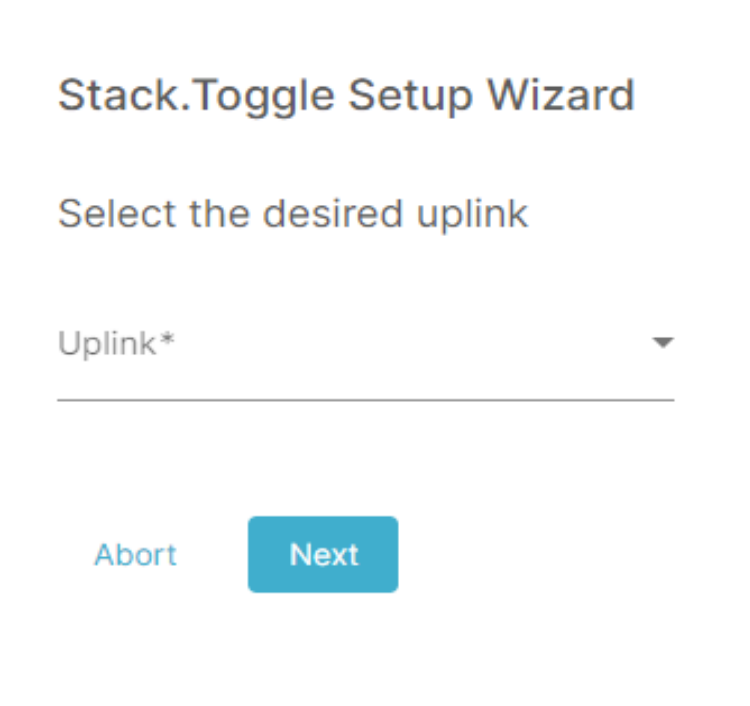
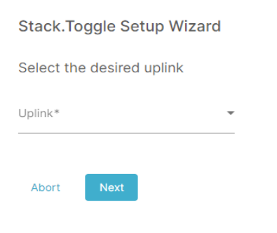
Uplink
In the first step of the wizard, the user will be asked to select the uplink type.
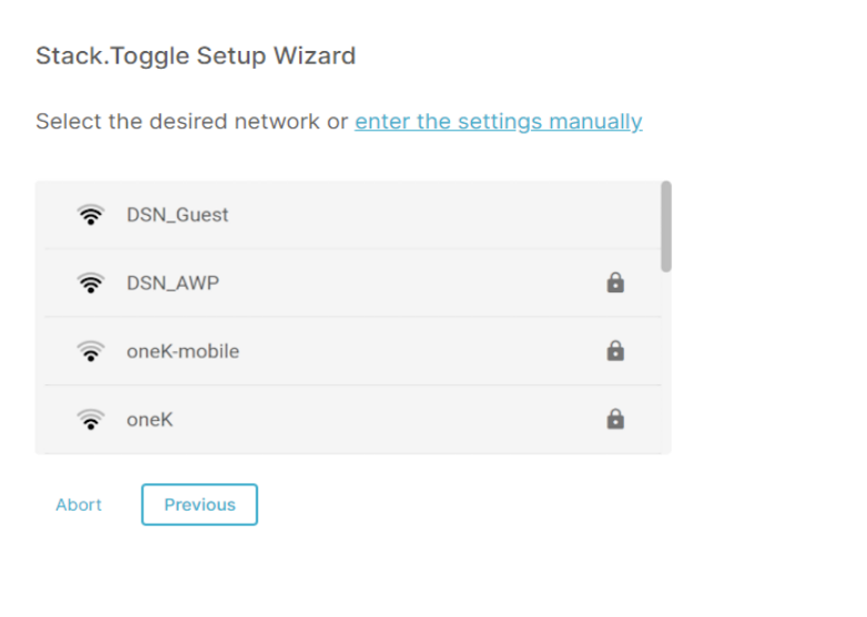
Network selection
Then the user will be asked to select the network from a list of all the available networks. The user can select a network by clicking on the corresponding network. It's also possible to manually configure the network settings by clicking the 'enter the settings manually' at the top.
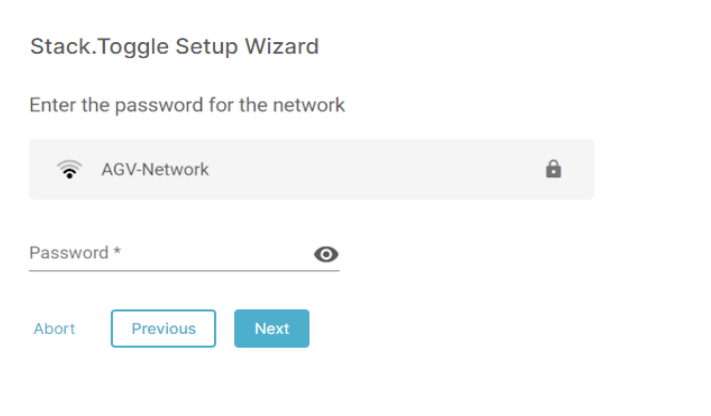
Authentication
The next step will be to enter the authentications details for the network. This step depends on the authentication type of the selected network.
For PSK networks, the user just needs to enter the password for the network.
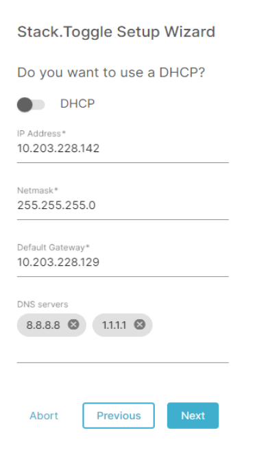
IP configuration
The next step in the wizard is the configuration of the IP address. This can be configured manually or via DHCP (if the network supports DHCP). For the manual configuration, the user has to enter the IP address with the corresponding netmask and the default gateway.
It's also possible to enter DNS servers, but that's not required. The input fields have validation for the entered IP addresses to check if the IP or netmask is valid.
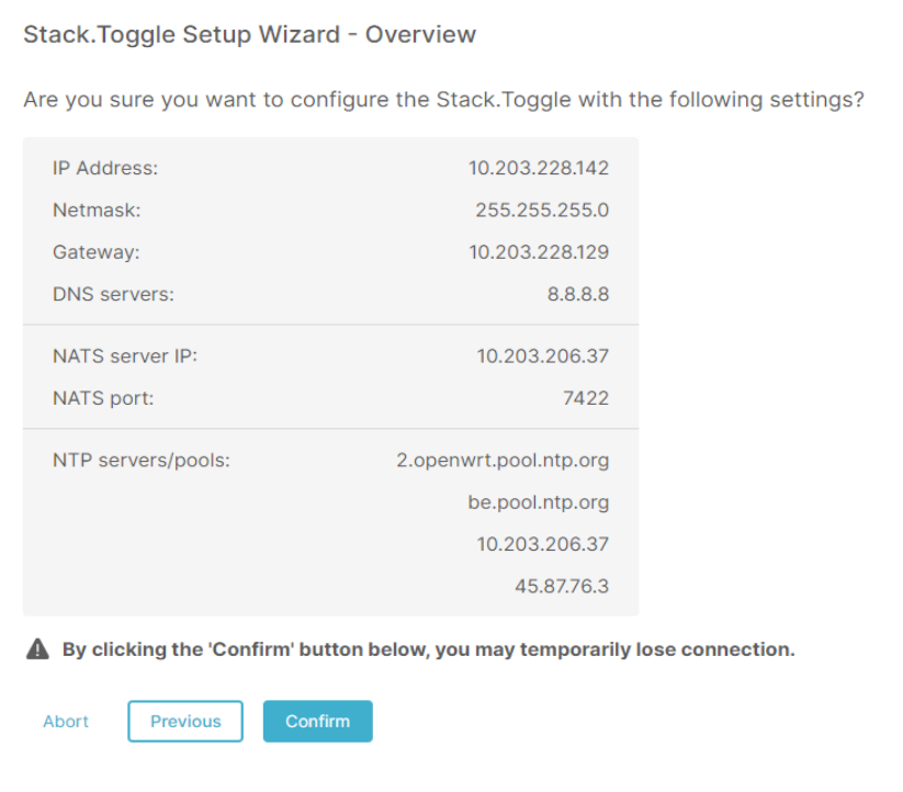
Confirmation
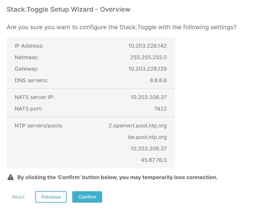
At the end, the user gets an overview of all the settings he entered. Here the user can confirm the new configuration after which the new Wi-Fi config will take place and the user will be redirected to the status page again.
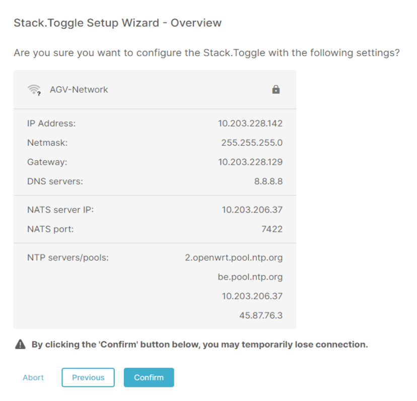
This overview screen also contains a warning that you can lose connection to the toggle temporarily when 'Confirm' button is clicked.
Ethernet
Uplink
In the first step of the wizard, the user will be asked to select the uplink type.
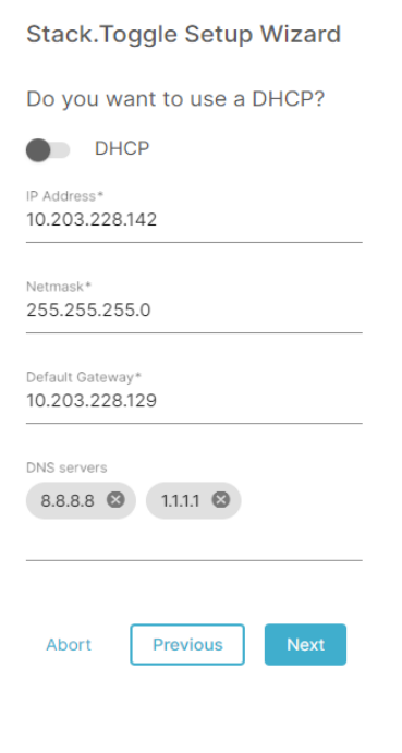
IP configuration
The next step in the wizard is the configuration of the IP address. This can be configured manually or via DHCP (if the network supports DHCP). For the manual configuration, the user has to enter the IP address with the corresponding netmask and the default gateway.
It's also possible to enter DNS servers, but that's not required. The input fields have validation for the entered IP addresses to check if the IP or netmask is valid.
Confirmation
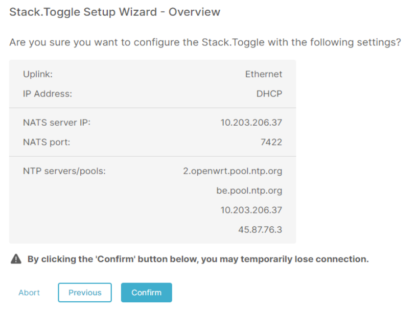
At the end of this configuration, the user will again see the overview of the new configuration and can confirm to enable the new config.
NATS Connection
NATS server
To configure an upstream NATS connection (to the fleetserver), the user has to enter the IP and the port of the NATS server. The port will be prefilled with the default port (7422), but can be changed if needed. The IP field is required and also has basic validation to check if the entered IP is valid.
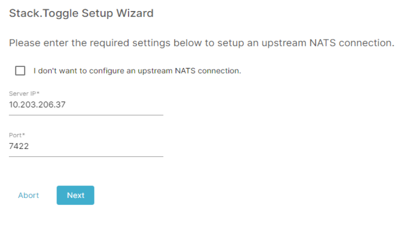
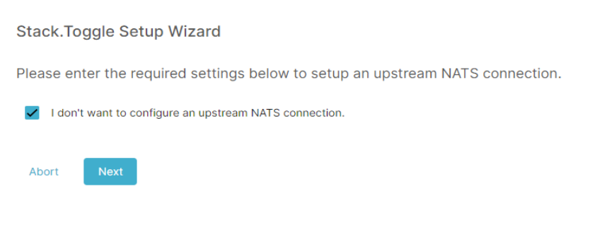
If, for example, a third party fleetmanager is used, it could not be necessary or possible to set up an upstream NATS connection. In that case, the user can select the checkbox to not configure a NATS connection and the NATS connection will be disabled.
Confirmation
At the end of this configuration, the user will again see the overview of the new configuration and can confirm to enable the new config.
Time syncing
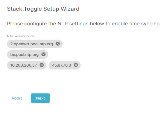
NTP servers and pools
To configure the time syncing between the toggle and an external source, the user can specify one or more NTP servers, and/or NTP pool. When the user already entered the configuration for the NATS connection (entered the IP of the fleetserver), this IP address will be prefilled in the list with NTP servers. The user can leave it there if the fleetserver has an NTP server to sync the time with, or delete it if that's not the case.
Confirmation
At the end of this wizard, there's also the overview screen, where the user has to confirm the new configuration.